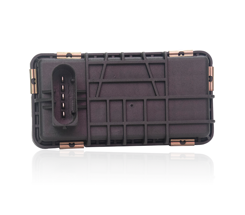
Pneumatic actuators are actuators that use air p […]
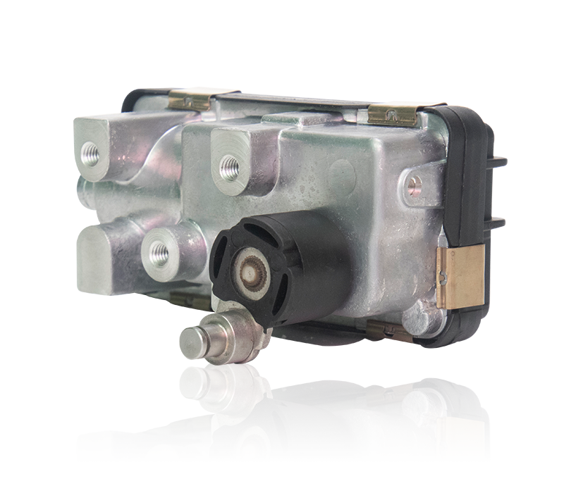
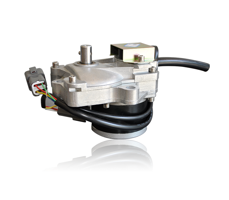
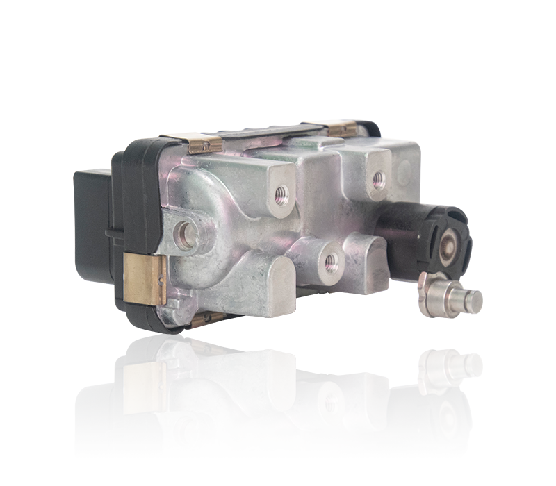
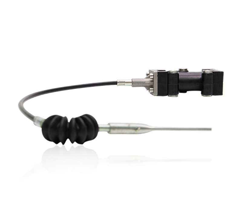
Pneumatic actuators are actuators that use air pressure to drive opening and closing or adjusting valves. They are also called pneumatic actuators or pneumatic devices. They are generally called pneumatic heads. Pneumatic actuators have two strokes, one is 0-90° stroke for use with butterfly valves, ball valves and other angle control valves, the second is for straight stroke structure, matching single-seat regulating valves, globe valves, gate valves, etc. We can equip pneumatic actuators with certain auxiliary devices according to the requirements of on-site industrial control, such as limit switches, reversing solenoid valves, handwheels, positioners, filter pressure reducing valves, etc. to cut off the pipeline fluid and adjust the flow rate. .
Install pneumatic actuator:
A. Install the sealing ring: there is a card in the middle position inside the top of the cylinder, install the sealing ring.
B. Install the connecting shaft: Insert from the bottom of the cylinder upwards. Pay attention to stringing the positioning block in before inserting the top. Install the sealing ring and snap ring to fix the connecting shaft.
C. Piston installation: Piston has two sets of directions, one is clockwise to close and counterclockwise to open; turn 180 degrees, clockwise to open and counterclockwise to close. Different directions lead to different switching states of the valve. Normally, the forward and reverse opening directions are used. Install the piston into the cylinder.
D. Adjust the angle of the connecting shaft: Use a wrench to adjust the connecting shaft to turn the piston out. Several attempts can be made. Until the piston reaches the bottom, the groove of the connecting shaft is a little bit left perpendicular to the cylinder.
E. Install positioning screws:Two positioning screws are installed above the cylinder, one is open and the other is closed.
When the connecting shaft cannot rotate, it means that the angle of the positioning block in the cylinder is wrong. After loosening the fixing screw, turn the connecting shaft 180 degrees, push the piston and tighten the fixing screw. After adjustment, you can turn it to show that the angle is no problem.
Rotating the connecting shaft groove parallel to the cylinder is the fully open position. If the groove of the rotating connecting shaft is perpendicular to the cylinder, the fully closed position indicates that the piston is installed.
F. Install the side cover: Note that the gasket on the cylinder cannot be dropped. If the cylinder is dropped, leakage will occur. The O-ring on the side cover also plays a role of sealing. Close the side cover, install the fixing screws and tighten them.
Debug pneumatic actuator:
Install the air supply connector (wrap the raw tape clockwise on the thread). The two holes are the air inlets of the switch valve. Open the valve intake port, close the valve intake port, exhaust; close the valve intake port, open the valve intake port, exhaust, they are mutual.
Connect the air source and test the opening position. When the groove of the connecting shaft is not parallel to the cylinder, the opening is over. Disconnect the air source, adjust the opening screw on the top of the cylinder, turn it inward, and tighten the fixing screw after adjustment.
Test the closing position. When the connecting shaft groove is not perpendicular to the cylinder, the closing position needs to be adjusted. Tighten the closing screw on the top of the cylinder, and tighten the fixing screw after adjustment. After adjustment, test whether the position of the connecting shaft between the closed position and the open position is correct.
https://www.fcfuda.com/
About Us
Products
contact us

Copyright © 2019 Fengcheng Fuda Auto Sensors Co.,Ltd. All rights reserved. Hella Turbo Actuator Manufacturers. Support: HWAQ