1. Installation of electric actuator motor 1. In […]
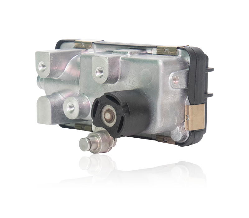
1. Installation of electric actuator motor
1. Install the motor, first install the motor in the coil, rotate the motor, and check whether the motor selection is easy.
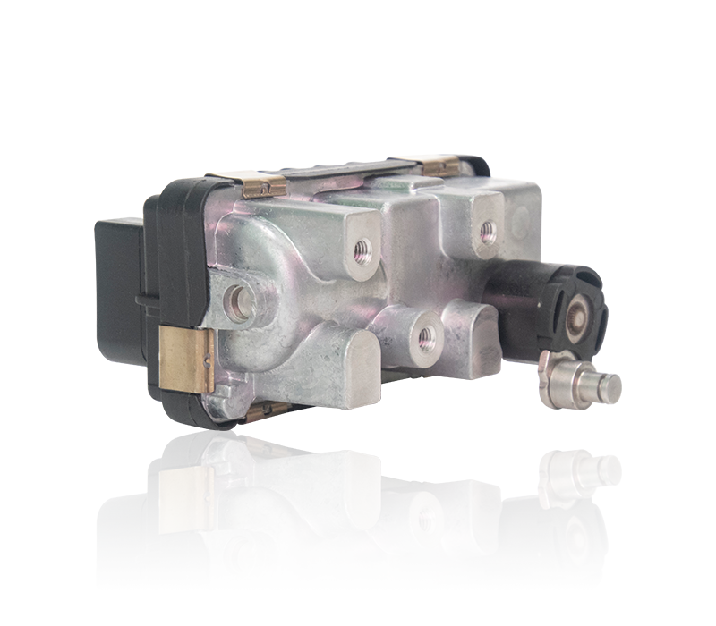
2. Install the motor to fix the baffle. The gap is relatively small. Special tools are required to knock the baffle in evenly.
3. After the fixed baffle is knocked in, install the 4 fixing screws of the baffle
4. After installing the fixing screws, rotate the motor again to check whether the motor rotates easily. (If the rotation is tight, you need to use a rubber hammer to hammer the motor down a few times)
5. Install the gear fixed bearing.
6. Fix the motor control line.
7. Install the support screws. (Convenient for later debugging)
2. Fine manual work (various wire connections)
1. Fix the capacitor, place the capacitor in a good position, and install the fixing screws.
2. Fix the capacitor with a cable tie first. After fixing, cut off the excess cable tie.
3. Connect the capacitor in parallel in the control line
4. Then install the control wire on the micro switch.
5. Place the micro switch and fix it with screws.
6. Arrange the wires, install the wires in the terminals, and fix the wires with glue.
3. Detailed technical activities
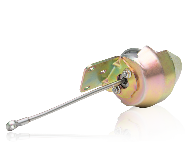
1. Install the mechanical positioning screw and rotate the switch at two angles to achieve the fully open and fully closed position. There is a gap of about 3mm between the positioning block and the mechanical positioning screw.
2. Install the cam (it is in contact with the micro switch); the installation of the two cams must be staggered by 90 degrees (the open position and the closed position must correspond); two positions: the open position and the closed position (the closed position cam corresponds to the mechanical positioning of the closed position, The open position cam corresponds to the open position mechanical positioning); four micro switches, two in one group, one group is for feedback control, and the other group is for power-off.
3. Install the gear set with lubricating oil, and connect the motor and the worm gear to achieve the linkage function.
4. Connect the electricity, test the valve switch, use a multimeter to test the feedback of the open position and the closed position.
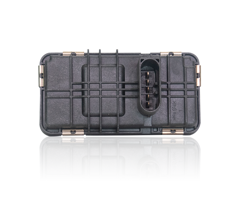
4. Install the box cover
1. Install and fix the side end cover.
2. Install and fix the electric actuator indicator cover.
3. Install the top end cover and fix it
4. Connect the valve control line to the terminal and fix it.
5. Install the terminal cover and fix it.
https://www.fcfuda.com/
About Us
Products
contact us

Copyright © 2019 Fengcheng Fuda Auto Sensors Co.,Ltd. All rights reserved. Hella Turbo Actuator Manufacturers. Support: HWAQ