The flange electric ball valve is an electric automatic […]
The flange electric ball valve is an electric automatic control valve composed of a quarter-stroke electric actuator and a flange ball valve. It is usually used for remote opening and closing (connecting and cutting off the medium) of the pipeline medium and the control of the flow rate. Flange electric ball valve is a full-bore valve with no obstacles inside the valve cavity, which is suitable for working conditions requiring large flow. The electric ball valve has a simple structure and consists of only a few parts, which saves data consumption; it is easy to operate and agile, and it can be opened and closed quickly by rotating 90°; and it also has good flow regulation and sealing characteristics.
Composition of flange ball valve
The main structure of the flange ball valve is composed of the valve body, the valve core and the valve stem. The spool material is 304, 316, 316L. Generally can be used for water, oil, steam, non-corrosive and other media.
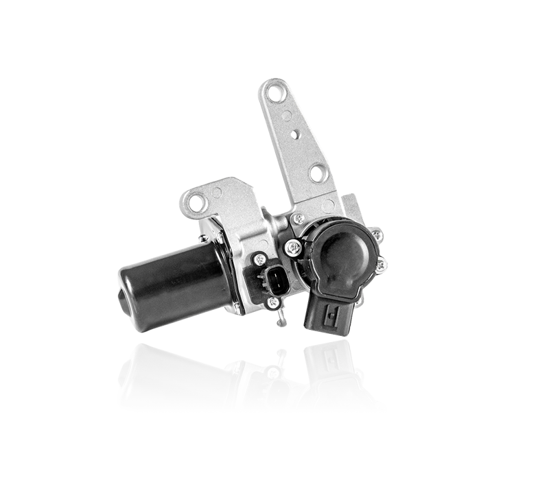
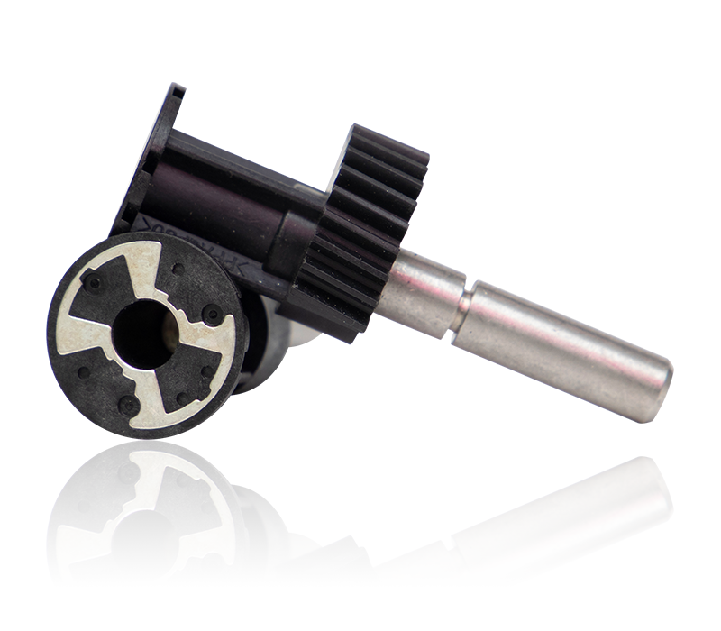
Electric Actuator
The electric actuator is composed of a motor, a gear, and a worm gear. The electric actuator realizes the remote control of valve opening and closing according to the automatic control on site, without manual operation, and has higher reliability and safety.
Installation of electric ball valve
Below the electric actuator is the inner octagonal groove, F05 center hole distance, above the ball valve is the square shaft, center hole distance F05, the size of the two connecting shafts is 14, directly install the two, and finally install the fixing screws and tighten them.
Electric ball valve test
Open the terminal box cover of the electric actuator. The POE electric actuator is a switch type with 6 terminals. There is a wiring diagram in the box cover, which can connect the lines of the valve according to the wiring diagram. Port 123 is connected to the control line of the ball valve, port 456 is connected to the feedback line of the ball valve to the system.
Turn on the power (the self-made small controller is connected in the video), test the valve, test the open position, turn on the power, and the indicator needle at the top of the electric actuator rotates in the open direction. The indicator light for power on is on, the pointer of the actuator points to the OPEN position, and the ball center of the ball valve is in the open position, indicating that there is no problem with the valve open position. Test the closed position, the valve is closed, and the indicator needle at the top of the electric actuator rotates in the closed direction. The indicator light of the power off is on, the pointer of the actuator points to the SHUT position, and the ball center of the ball valve is in the off position, indicating that the valve is closed.
https://www.fcfuda.com/
About Us
Products
contact us

Copyright © 2019 Fengcheng Fuda Auto Sensors Co.,Ltd. All rights reserved. Hella Turbo Actuator Manufacturers. Support: HWAQ